





Electromechanical Systems Integration: Matching Motion, Sensors, and Controls
A motor can meet its torque specification, a sensor can deliver precise readings, and a controller can execute commands—yet the complete machine may still miss its performance targets. Effective electromechanical systems integration depends on matching these components under real operating conditions, not simply comparing datasheets. The critical questions involve load dynamics, feedback accuracy, control-loop response, communication compatibility, and safety requirements.
Consider a packaging axis that reaches its commanded position but takes too long to settle, or an adhesive dispensing system whose pump responds correctly while material flow lags behind. Neither problem necessarily indicates a defective component. The mismatch may sit between the mechanical process, the measurement location, and the control strategy. A useful evaluation therefore starts with what the machine must accomplish, then works backward through the complete system.
Define performance at the load, not at the motor
“Positioning accuracy” is incomplete unless it identifies where position is measured, under what load, and at which point in the cycle. Accuracy at a motor shaft is not necessarily accuracy at a gripper, cutting tool, or conveyor surface. Gear backlash, coupling compliance, bearing clearance, and frame deflection can separate those results.
Before comparing hardware, establish an operating envelope that includes payload variation, travel, speed, acceleration, cycle sequence, ambient conditions, and allowable error. Distinguish repeatability from absolute accuracy, and settling time from travel time. A mechanism may return consistently to the same incorrect location; another may reach the right position eventually but miss the available process window.
The acceptance criteria should also identify abnormal conditions. A vertical handling axis, for example, needs a defined response to power loss. A pump may need protection against dry running or blocked discharge. These requirements influence the architecture before motor size or controller brand becomes relevant.
Match the drive to the complete motion cycle
Motor selection requires more than a comparison between rated torque and estimated load torque. Acceleration adds an inertia-dependent demand, while friction, transmission losses, and process forces vary with operating conditions. Review the required torque across the motion profile against the motor-drive combination’s available torque-speed envelope.
Peak capability and continuous capability answer different questions. Peak torque may cover acceleration, but repeated acceleration can still create a thermal problem. RMS torque is useful for evaluating cyclic thermal loading when applied within the manufacturer’s assumptions. Cooling arrangement, enclosure temperature, mounting, and low-speed operation can change what the assembly can sustain.
Transmission selection introduces another trade-off. A higher gear ratio can reduce reflected load inertia and increase output torque, but it also changes available output speed and may introduce backlash or compliance. There is no universally correct inertia ratio for every servo axis; acceptable behavior depends on mechanical stiffness, tuning, motion demands, and drive capability.
Check what happens during deceleration as well. Regenerative energy may require suitable handling through the drive’s DC bus, braking resistor, or another approved arrangement. On gravity-loaded axes, distinguish a holding brake from a brake rated for repeated dynamic stopping. Treating the two as interchangeable can create both reliability and safety problems.
Choose feedback that represents the process
Sensor resolution is often the easiest specification to compare—and one of the easiest to overvalue. Fine encoder increments do not remove mechanical error, installation misalignment, electrical noise, or temperature drift. Evaluate measurement accuracy, repeatability, update rate, latency, and environmental limits separately.
Measurement location matters just as much. Motor-mounted feedback can support effective shaft control while leaving downstream movement unobserved. Load-side feedback can expose transmission error, but closing a loop around a flexible mechanism may require a different control strategy. More feedback is not automatically better feedback.
The useful system view follows the command through the controller, drive, motor, transmission, and load, then traces the measured signal back. Marking delays and unmeasured mechanical elements on this path often reveals why apparently compatible components fail to deliver the required result.
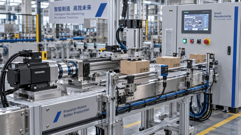
For process equipment, the controlled variable may be pressure, flow, tension, or force rather than position. Pump speed alone does not establish delivered flow when viscosity, back pressure, or leakage changes. Similarly, conveyor motor feedback does not necessarily describe web movement if slip occurs. Select sensing around the process variable that determines acceptable output.
Verify the whole signal path
Compatibility checks should cover supply voltage, signal type, input circuitry, connector assignment, cable requirements, and diagnostic behavior. An incremental encoder interface and an absolute encoder interface are not interchangeable simply because their connectors look alike. For analog measurements, verify scaling, input range, grounding, and the response to a broken wire or out-of-range signal.
Filtering deserves explicit review. It can stabilize a noisy reading, but it also introduces delay. A heavily filtered signal may look reassuring on a trend display while responding too slowly for the control loop or fault-detection requirement.
Control timing is an end-to-end requirement
A fast controller does not guarantee fast machine response. The effective delay includes sensor acquisition, communication, task scheduling, command processing, and actuator response. Timing variation, or jitter, can matter as much as average latency when several axes must coordinate.
Many servo systems use nested current, velocity, and position loops, often with the faster inner loops executed in the drive. The machine controller handles coordination and sequencing. Establish where each loop runs and what timing assumptions it depends on before assigning responsibilities between devices.
Communication compatibility also extends beyond the protocol name. Two devices supporting EtherCAT, PROFINET, or another industrial network may still differ in supported profiles, synchronization features, process-data mapping, firmware behavior, and diagnostics. Obtain the relevant device documentation and confirm the specific operating mode needed for the application.
Do not compensate for weak mechanics by increasing controller gain indefinitely. Structural resonance, backlash, or a loose coupling can cause oscillation that tuning cannot reliably eliminate. Review mechanical integrity before interpreting every following-error event as a software problem.
Use standards to shape the design, not just the paperwork
Standards selection starts with the machine, its hazards, and its destination market. ISO 12100 provides a framework for machinery risk assessment and risk reduction. IEC 60204-1 addresses electrical equipment of machines. Where safety-related control functions are involved, ISO 13849-1 or IEC 62061 may be applicable, depending on the design and assessment approach. Confirm the relevant editions, local adoption, and any machine-specific requirements.
IEC 61800-5-2 addresses functional safety aspects of safety-related power drive systems. A drive’s Safe Torque Off function prevents torque-producing power from being supplied to the motor; it does not provide electrical isolation or guarantee an immediate stop. A suspended load can still move under gravity unless the system includes suitable measures.
Required safety performance must follow the risk assessment. A safety-rated drive or sensor does not make the entire machine compliant by itself. Architecture, wiring, diagnostics, failure behavior, configuration, and validation all affect the implemented safety function.
Environmental ratings need similar care. An IP classification under IEC 60529 addresses enclosure protection against specified ingress conditions, not every chemical exposure, washdown practice, or corrosion mechanism. Electromagnetic compatibility also depends on installation: cable routing, shielding, bonding, and separation of power and signal circuits can determine whether otherwise suitable components operate reliably together.
Turn integration assumptions into acceptance tests
A successful no-load demonstration is weak evidence for production readiness. Test the operating envelope and retain records that distinguish mechanical, electrical, and control-related limitations. Useful acceptance checks include:
- Run representative cycles with minimum and maximum intended loads, recording position error, settling behavior, current, and relevant process measurements.
- Continue operation long enough to assess thermal behavior, rather than relying on a brief peak-performance run.
- Verify startup, homing, restart, and recovery after permitted fault conditions, including communication loss and sensor faults where safely testable.
- Validate safety functions through an approved procedure, with defined expected responses and documented results.
- Confirm that alarms identify actionable causes and that maintenance staff can retrieve configurations and replace components without undocumented adjustments.
Agree on these tests before final component approval. Otherwise, suppliers and machine builders may each demonstrate compliance against different assumptions. Record firmware versions, drive settings, sensor scaling, network configuration, and mechanical revisions alongside the results. A test report is much less useful if the tested configuration cannot be reconstructed.
Keep replacement and sourcing decisions tied to system behavior
A replacement motor with the same power rating may have different inertia, feedback, or thermal characteristics. A substitute sensor may change latency or fault signaling. Even a bearing or coupling change can alter alignment, stiffness, and vibration. Define which substitutions require document review, retuning, or partial revalidation rather than treating every form-fit replacement as functionally equivalent.
The Global Industrial Finishing & Essentials (GIFE) organizes product knowledge, technology developments, and supply-chain information across electromechanical equipment and supporting industrial categories. That cross-category perspective is useful when integration choices involve motors, pumps, bearings, fasteners, or materials—not only electronics. Market intelligence can help identify alternatives and availability risks, while project-specific engineering evidence remains necessary to approve them.
Before approving an electromechanical system, request three connected deliverables: an operating-envelope specification, an interface and safety requirements record, and an acceptance-test plan. If a critical requirement cannot be traced through all three, the design still contains an assumption that needs resolving before delivery.
Related News
- 00
0000-00
How to prevent delamination in laminated flexible packaging films - 00
0000-00
Fujifilm and ePac Partner Globally on Jet Press FP790 Deployment - 00
0000-00
Choosing technical ceramics for wear resistance under impact loads - 00
0000-00
Which compliance standards apply to children's stationery in the US? - 00
0000-00
How to assess a furniture components supplier’s production capacity
Weekly Insights
Stay ahead with our curated technology reports delivered every Monday.