





A packaging axis can look perfectly matched on paper: the motor reaches the required speed, the reduction ratio fits, and the gearbox’s advertised torque exceeds the calculated load. Yet during commissioning, the axis may run hot, hesitate after reversing, or miss its settling-time target. The problem is often not a defective component, but a selection process that treated several different ratings as interchangeable.
Selecting a gearbox for automation systems means balancing torque capacity, backlash, and duty cycle against positioning accuracy, thermal limits, and service life. For technical evaluators, the useful question is not simply “Will this gearbox move the load?” It is “Will it deliver the required motion, repeatedly, under the actual operating conditions?” That distinction turns a catalog comparison into an engineering decision.
Build the motion profile before comparing gearboxes
Start with the machine cycle rather than a preferred gearbox type. A conveyor operating steadily, a printing feed reversing frequently, and a furniture-component positioning axis holding against machining forces may require similar output torque but very different transmission characteristics.
The application record should identify:
- Motion requirements: output speed, travel, acceleration, deceleration, reversal frequency, and settling time.
- Load conditions: moving mass, rotational inertia, friction, gravity loads, process forces, and possible jams or impacts.
- Operating schedule: cycle duration, dwell periods, hours per shift, and expected lifetime cycles.
- Installation constraints: mounting orientation, available space, ambient temperature, contamination, and maintenance access.
- Acceptance criteria: positioning accuracy, repeatability, permissible vibration, and allowable operating temperature.
Record the torque and speed for each phase of the cycle. Do not assume a dwell is an unloaded interval: a vertical axis may need holding torque throughout a pause. Conversely, holding torque at zero speed does not produce the same gearbox losses as transmitting that torque at high speed.
This profile also makes supplier discussions more productive. “Intermittent operation” is vague; a documented sequence of acceleration, travel, braking, and holding gives an application engineer something meaningful to verify.
Torque capacity: distinguish working loads from exceptional events
Gearbox catalogs may list nominal, acceleration, peak, and emergency-stop torque. These terms are not universally defined. A peak rating may be permitted only for a specified duration and number of occurrences, while an emergency rating may describe a rare event rather than a repeatable operating condition.
Calculate torque at the correct shaft
At the gearbox output, required torque generally includes process torque, friction, gravity where applicable, and torque needed to accelerate the load:
Tout = Tprocess + Tfriction + Tgravity + Jload × αout
These are signed quantities, so gravity or process forces may assist motion in one direction and oppose it in another. Linear mechanisms require conversion through the pulley radius, screw lead, or other transmission geometry, with the mechanism’s efficiency included appropriately.
For a reduction ratio i = motor speed / output speed, the motor torque needed to transmit an output load is approximately Tout / (i × η) during motoring, where η is gearbox efficiency. Motor and gearbox input-side inertia add acceleration demand. Backdriving and regenerative operation require separate consideration; do not apply the motoring relationship indiscriminately.
A higher ratio reduces reflected load inertia approximately by 1/i², but increases the motor speed required for a given output speed. It can also change gearbox efficiency, input inertia, and available torque ratings. Ratio selection is therefore a motor–gearbox matching exercise, not simply a way to multiply torque.
Use RMS torque as a screening tool, not a universal rating check
For a segmented cycle, root-mean-square torque can be calculated as:
TRMS = √[Σ(Tk² × tk) / Σtk]
Consider an illustrative output cycle: 60 Nm for one second, 20 Nm for three seconds, and zero torque for two seconds. Its RMS torque is approximately 28 Nm, although its peak is 60 Nm. Both values matter, but neither alone proves gearbox suitability.
RMS torque is useful for motor thermal assessment and preliminary comparison. Gearbox tooth and bearing life may require a manufacturer-specific equivalent-load calculation using different weighting and speed dependence. Thermal suitability also depends on input speed, efficiency, mounting, and cooling conditions.
Ask the supplier to verify the complete cycle against fatigue, peak-load, and thermal limits. Add application-specific allowances for uncertain friction, impacts, and process variation rather than applying an arbitrary safety multiplier and assuming every risk is covered.
Backlash is only one part of the positioning error
Backlash describes clearance that produces lost motion when torque direction changes. In a reversing axis, the motor may rotate before the output engages the opposite tooth flank. This is particularly relevant to indexing, registration, pick-and-place, and bidirectional positioning.
To connect a catalog value with machine performance, convert angular clearance into displacement at the working point. For a rotary output driving a pulley:
Linear lost motion ≈ pulley radius × backlash angle in radians
One arcminute is approximately 0.000291 radians. At a 50 mm pulley radius, three arcminutes correspond to roughly 0.044 mm of theoretical lost motion. This illustration excludes belt stretch, coupling compliance, bearing movement, and structural deflection.
Those exclusions matter. A low-backlash gearbox can still twist under load. Approximate elastic angular deflection is θ = T/Kt, where Kt is torsional stiffness expressed in compatible units. Unlike clearance, elastic deflection changes with applied torque and may influence settling, disturbance rejection, and control stability.
Accuracy, repeatability, backlash, and stiffness are related but not interchangeable. An axis approaching from one direction may repeat consistently despite clearance. The same axis approaching from alternating directions may show a larger spread. Changing process loads can introduce further error through elastic deformation.
Compare backlash values only after checking measurement conditions: applied test torque, shaft position, temperature, and whether the specification applies to a new unit or expected service condition. Output-side feedback can correct some transmission error, but it does not eliminate compliance or guarantee stable high-bandwidth control.
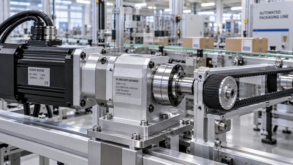
Duty cycle: why a gearbox that survives a peak can still overheat
Mechanical strength and thermal capacity are separate constraints. A gearbox may withstand a brief high torque yet be unsuitable for sustained high-speed operation. Gear meshes, bearings, seals, and lubricant generate losses that must leave through the housing and surrounding structure.
Duty cycle is therefore more than the percentage of time an axis moves. Two axes can operate for the same fraction of each minute while generating substantially different heat because their speeds, loads, reversal patterns, and dwell conditions differ.
For thermal assessment, check:
- Continuous and maximum input speeds, including restrictions associated with the selected ratio.
- Thermal ratings and the ambient temperature, mounting arrangement, and cooling assumptions behind them.
- Lubricant suitability for temperature, orientation, start frequency, and maintenance intervals.
- Whether the gearbox sits inside an enclosure or near another heat source.
- The expected temperature after sustained operation, not just during a short commissioning test.
Catalog efficiency should also be treated carefully. A single value may represent favorable operating conditions and may not describe low-load running, cold starts, or every ratio. Ask for operating-point data when losses are important to the decision.
Repeated acceleration introduces another constraint: fatigue exposure. A short cycle with thousands of reversals can be mechanically demanding even if its average temperature remains acceptable. Thermal verification and life assessment should proceed together.
Which gearbox architecture fits the motion?
Architecture narrows the shortlist, but it does not replace product-level evaluation. Different designs within the same family can have substantially different stiffness, load capacity, and allowable speed.
A continuously running packaging conveyor may favor efficiency and thermal headroom over extremely low backlash. A registration axis may place greater weight on reversal behavior and stiffness. A robotic joint may need both compact reduction and carefully verified moment-load capacity.
The interface checks that prevent expensive redesigns
A gearbox can pass the torque calculation and still be wrong for the machine. Output bearings must support radial loads, axial loads, and overturning moments from pulleys, pinions, or cantilevered tooling. Permissible radial load usually depends on its distance from the bearing support, so shaft-load calculations need the actual geometry.
Also verify motor flange compatibility, shaft engagement, coupling torque capacity, alignment requirements, and mounting-face rigidity. A flexible bracket or poorly aligned connection can undermine the performance of an otherwise suitable precision gearbox.
Vertical axes deserve a separate safety review. Gear friction is not a substitute for an appropriately designed brake or load-holding arrangement. Assess power loss, brake location, backdriving, emergency stopping, and credible mechanical failures within the machine’s overall safety design.
For sourcing teams, replacement availability and maintenance requirements belong in the evaluation too. A technically attractive unit may introduce avoidable production risk if its mounting interface is difficult to replace or its lubrication procedure cannot be performed in the installed position.
Turn the shortlist into a defensible decision
Send each supplier the same motion profile and ask for written confirmation of the proposed model and ratio. The response should distinguish continuous operation, repeated acceleration, exceptional stops, output bearing loads, and thermal suitability. An unqualified “torque rating meets requirement” is not enough.
Then validate the critical assumptions on representative hardware. Run the intended cycle long enough to assess temperature stabilization, following the supplier’s measurement guidance. Measure bidirectional positioning and settling under realistic loads, not just with an unloaded axis. Where relevant, test cold starts, sustained production, and the worst credible process condition.
The final choice should have three clear foundations: verified load capacity, demonstrated motion performance, and acceptable sustained-operation behavior. This is the practical product-evaluation approach emphasized by GIFE: make component specifications meaningful at the machine level. The right gearbox for automation systems is not necessarily the one with the highest peak torque or smallest backlash number. It is the one whose limits and trade-offs match the work the axis must perform.
Related News
- 00
0000-00
How does order volume affect the price of self-adhesive label materials? - 00
0000-00
How backlash affects precision mechanical transmission accuracy - 00
0000-00
How Do You Choose Drawer Slides for Heavy Storage? - 00
0000-00
Choosing a Gearbox for Automation Systems: Torque, Backlash, and Duty Cycle - 00
0000-00
What to verify before choosing a furniture connectors supplier
Weekly Insights
Stay ahead with our curated technology reports delivered every Monday.